3D printer DIY? or Buy? or... Part 2
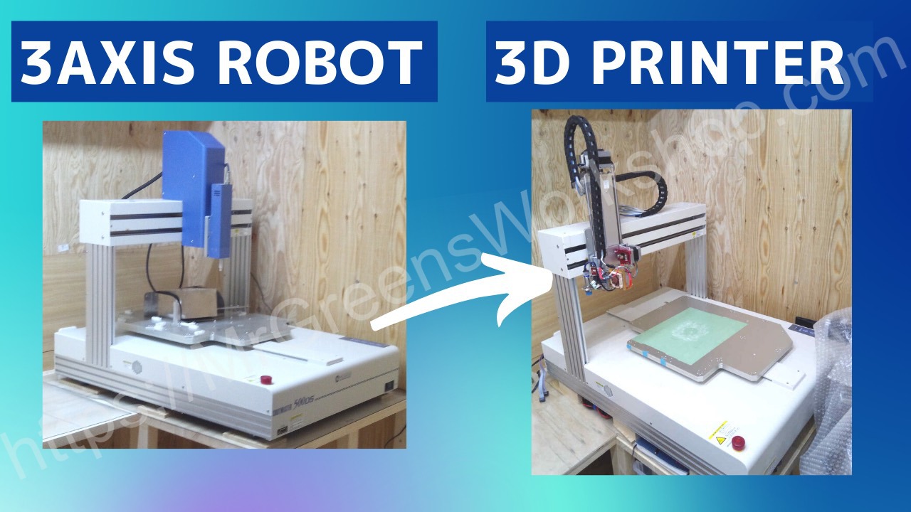
If you haven’t read the part 1, please check it out. In this post I will talk about what problems I dealt with and how much it cost. After long search I found a 3 axis robot at an online auction. It was just 10 bucks. I had to pick it up and it took 3 hours to drive but it was worth it. I have already released a YouTube video, so please take a look.
Tear down
After tear down the robot, here is what I found…
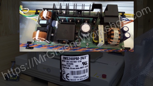
It has 24V 10 Amps power supply
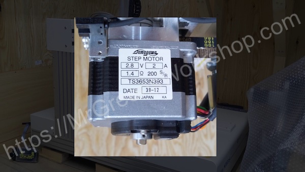
3 stepper motors with built in encoders
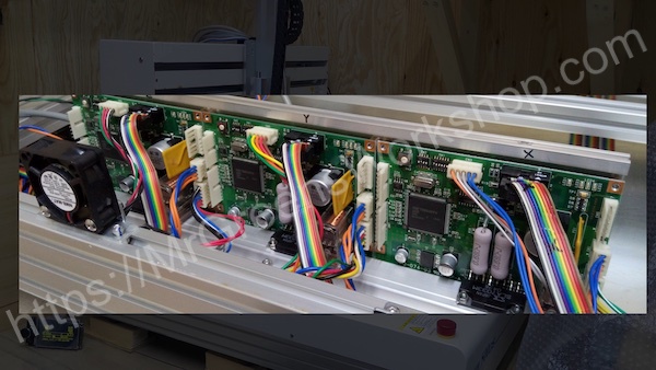
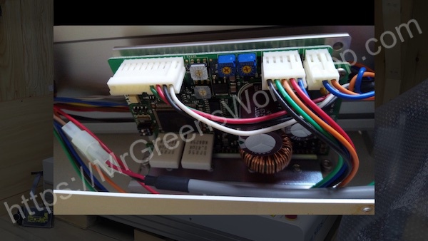
3 close loop motion controllers
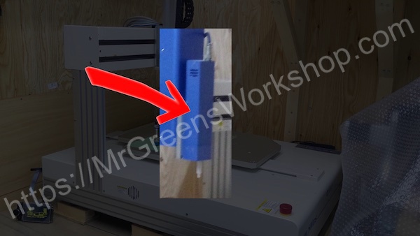
A stepper motor mounted on the Z axis
Stepper motor driver (Open loop)
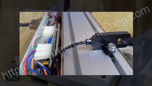
Optical limit switches for all 3 axises
Machine specs
Musashi Engineering Desktop robot ShotMaster 500DS
| Stroke | Resolution | Max Speed | |
|---|---|---|---|
| X,Y | 500mm | 4.2μ | 800mm/s |
| Z | 120mm | 1μ | 170mm/s |
I should say they made a great job. These machines shouldn’t be wasted. I know, it’s too good for 3D printer. I set a golden rule for myself which is, I will start buying the upgrade parts I mentioned in the part 1 and whenever I feel that the project will fail, I will use those upgrade parts in the new cheap 3D printer. But I should say I’m not a quitter.
Tasks and problems
Original controller is not usable
Robot has RS232C interface and specific protocol.
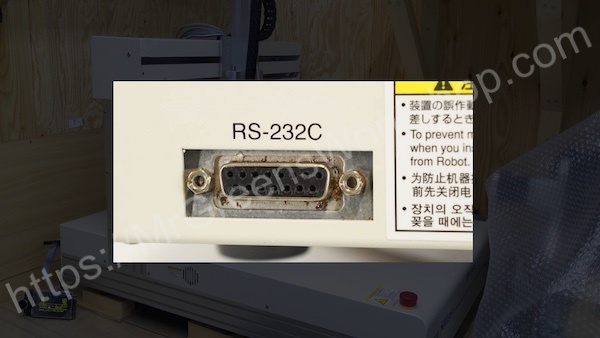
I was planning to change marlin firmware to send coordinates over RS232C. After digging marlin stepper pulse source code and asking about it marlin community in discord, I found that It’s not just moving each axis to desired position. Extra control pulses are used for retraction etc. I had to remove existing controller board and drive axises from 3D printer controller. Actually this made things simpler. Marlin will be full control of each axis. After digging some time I found motion controller pinouts.
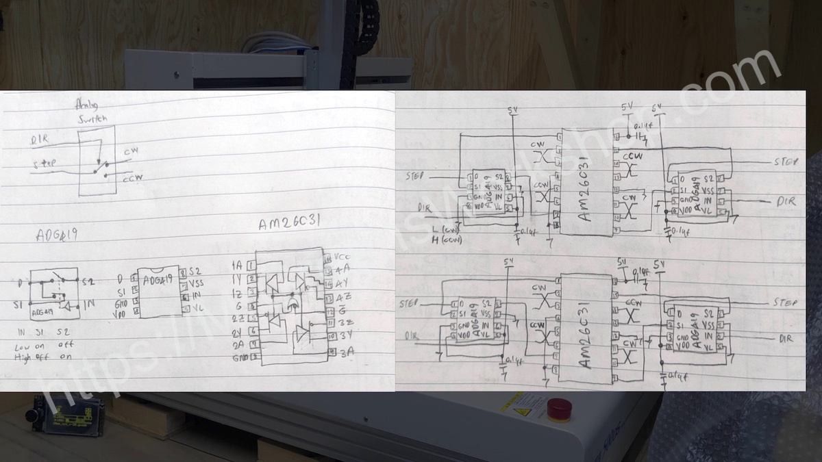
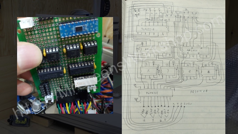
It uses RS422 for each direction. I made a circuit board to convert TTL direction and pulse signals to RS422 signals and connect between motion controllers and 3D printer controller. Schematic diagram looks like this.
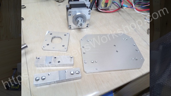
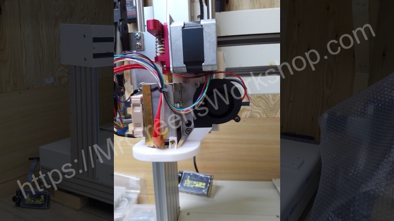
Making a direct drive extruder
I used the aluminum plate came with the machine and a few heatsinks as a material.
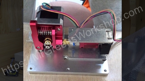
As I mentioned before we have 4th axis stepper motor, but it is too small for extruder feeder. I wanted to use the original stepper driver so I found 5 pole stepper motor at an online auction for 8 bucks. I also bought metal extruder feeder components and mounted on the stepper motor.
Upgrading extruder feeder stepper driver
After testing the extruder feeder stepper, it was skipping steps. I realized that the torque wasn’t enough. Checking the data sheet of driver, I found that the driver had current limit setting. Even at the maximum current setting, the torque wasn’t enough. I checked the Oriental motors catalog, they had another model for higher current.
| Driver model | Motor rated current |
|---|---|
| DFC5103P | 0.35 A/phase |
| DFC5107P | 0.75 A/phase |
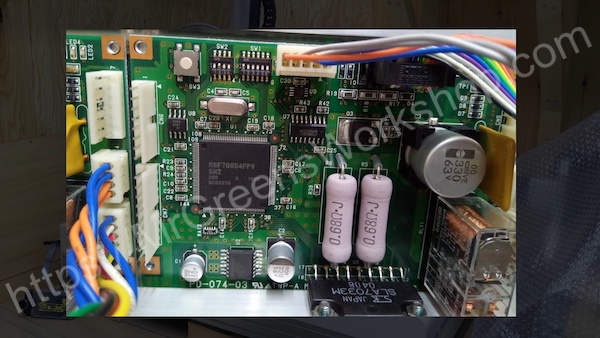
What component is used for current limiting? For sure Cement resistors. There were 2 on the driver board.
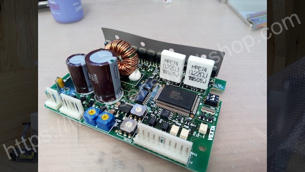
When I looked for higher current model, those resistor values were different from mine, so I ordered the resistors and changed it. It worked as I expected. With this, Oriental motor DFC5103P was upgraded to DFC5107P.
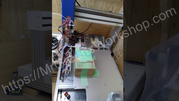
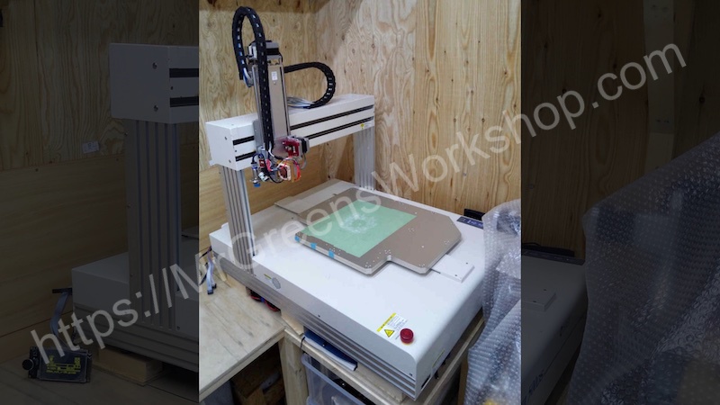
Putting all together
After finishing extruder I mounted that to the Z axis. Since the Z axis could only move 120mm, I had to raise the base, and to do so I used a cardboard for testing. Don’t judge me ok, I couldn’t find anything better than that.
The controller was ready, necessary cabling done, belt tensioning done, pid calibration done, step calibration done. Next step is printing something!
First print and layer shifting problem
I had to make sure I could use it as a 3D printer to continue further tasks. I printed the test cube. Here is what I got.
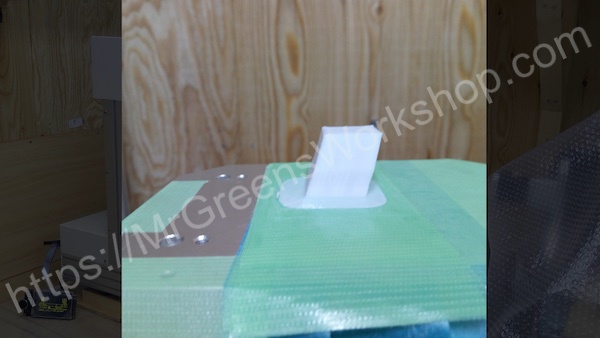
It was really frustrating. Everything seemed right. After asking marlin community in discord, one of them pointed me the right direction and told me that someone with external motor drivers had the problem before, and advised me a few things and one of them was inverting steps, and it did the trick.
#define INVERT_X_STEP true
#define INVERT_Y_STEP true
Upgrading the Z-axis
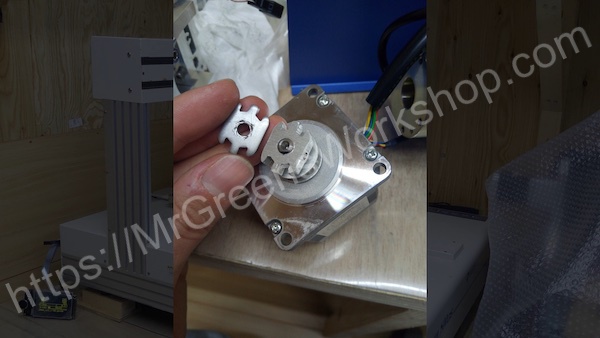
I had to replace Z axis with something else. I can’t print on cardboard forever, right? Then I started digging online auction once again, and I found IAI single axis Robo Cylinder for 25 bucks. The original controller was incompatible with pulse drive. The settings can be changed but I didn’t have the cable nor software. I decided to use IAI Robo Cylinder mechanic with the existing Z axis motor. I removed the motor and made a coupler identical to original one.
I made necessary parts to mount the extruder module to cylinder and cylinder to machine. After making motor mounting plate, I used hex spacers for mounting it.
Yeah! Mounting plate hole could be cleaner, but it just does the job and the mess isn’t visible when mounted. With this, maximum print area will be 500x500x200mm.
Safety feature
This machine has transition board on it. I manage to add electrical emergency stop feature by jumpering and adding some components. When the machine is powered on, it starts in emergency mode. Reset button needs to be pushed to release from emergency mode and power up the motion controllers. When emergency stop button is pushed, motion controllers are power-down. Even after releasing emergency stop button, reset button needs to be pushed to start the machine cycle. It’s one of the safety measures in industry, requiring 2 actions from the user.
Cable drag chain installation
Finally, the cabling. I bought the cable carriers for y and Z axises and mounted it. Cabling took quite some time. It wasn’t easy, but in the end it looks good, doesn’t it?
Part cooling duct
After searching on the Thingiverse, I found some designs. I imported the STL files to the Tinkercad and put all things together. This is the result.
Auto bed leveling
You may wonder about inductive proximity sensor mounted on the Z axis. After testing it, repeatability wasn’t good enough in my setup and currently I’m not using it.
Power consumption
After checking the power consumption, I think this power supply is sufficient for the job.
| State | Current |
|---|---|
| Idle(EMG on) | 0.638A |
| Servo on idle | 1.6A |
| Homing max | 1.6A |
| Nozzle temp 195C | 3A |
| Nozzle set temp reached | 2A |
| Printing max | 3A |
- Power Supply : 24V 10A (TDK LAMBDA ZWS240PAF-24)
- Heater       : 24V 1.66A (40W)
Final costs
Budget plan
Option 3  DIY + junk 3 axis robot + Upgrades

Junk 3 axis robot    : $60
Upgrades             : $160
Total cost           : $220
Actual costs
| 3 axis robot | junk | $10 |
| IAI Robo Cylinder | junk | $25 |
| Hotend | MK8 24V 40W | $22.67 |
| Hotend silicon cover | $1.76 | |
| Extruder | MK8 | $9.38 |
| Extruder feeder stepper | junk | $8 |
| Controller | Bigtreetech SKR v1.3 | $24.24 |
| Touch panel | Bigtreetech TFT 3.5 V3.0 | $31.28 |
| Cable drag chain | $16.97 | |
| Part cooler fan | 50x50x15mm | $3.87 |
| Extuder cooler fan | Noctua NF-A4x10 FLX | $17.95 |
| Signal converter pcb | $17.37 | |
| Parts on hand | $0 | |
| Total spend: | $188.49 |
Among the advantages I talked about in the part 1, for me being a maker, I think I was able to contribute to reducing the amount of waste from the perspective of the SDGs, which are the most important.
Close-ups
For other pictures such as making process, please check out my Instagram page. You can find in About page.
You Can Support My Work
Creating projects like this takes a great amount of time. Much appreciated if you consider supporting me so that I can continue projects like this and creating new contents for everyone.
You might consider supporting me via GitHub Sponsors, Patreon, or Ko-fi. For links, please see the About page.
Final words
Future plans, motor cover for Z axis, box for controller panel. These are what I can think of.